Low cost lock-in amplifier
Vivek Singh
EEGR 451
Digital Signal Processing
Dr. James Whitney II
Department of Electrical Engineering, Morgan State University, Baltimore, MD
17 February 2011
Abstract
A low cost lock-in amplifier has been designed and tested. The design parameters were considered such that the frequency of weak signal was ensured while testing. The phase shift of the detected weak signal due to the delay was measured.
1. Introduction
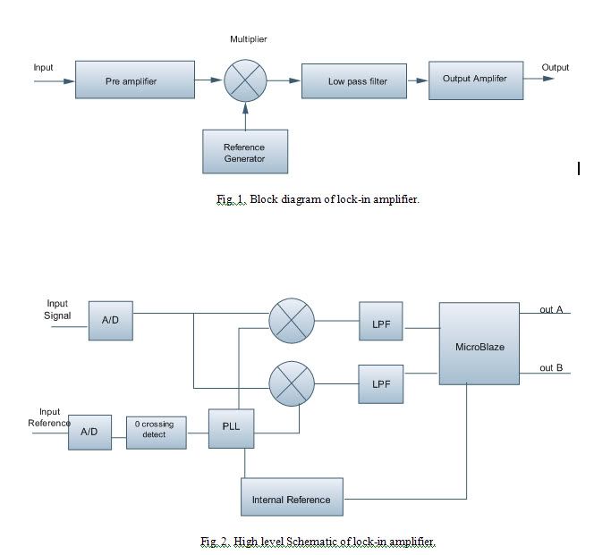
Lock in Amplifier is a device that provides a DC output proportional to the AC signal. It detects the very low signal of a particular frequency rejecting all other frequencies from a noisy environment. This device is very useful in measuring the phase shift of large signals with high signal to noise ratio. Initially, the signal is multiplied by a reference function, mixing through a frequency mixer and the result is filtered using a low-pass filter. For a signal Y (t) containing two frequencies when multiplied by the reference function R (t) the result is obtained X(t)
Lock-in Amplifier is very useful in detecting very small signals in presence of large background noise. However, it is very costly to obtain and perform the analysis on the lab. Considering a preferred design choice it can be easily build using microchips or even better using the programmable FPGA board to use it in a PC. Due to the high cost of microchips the FPGA logic for the Lock-in is build and tested.
2. Body/Proposed Work
The main objective of this research is to build all digital lock-in amplifier using FPGA board. It would be performed using the steps shown on Fig 1. Each of the physical components used on signal processing would be designed individually as VHDL modules. The rough algorithm is shown on Fig 2.
The other task would be to design a C programming module for the user interface. Once the amplifier is successfully built, the measurements have to be performed. It would be tested to measure the fluorescence lifetime and would be compared with the MATLAB simulation.
The raw data acquired from the oscilloscope would be saved and loaded into MATLAB and secondly to filter the raw data using the digital low pass filter using “cheby1” with normalized passband edge frequency. Then the filtered data would be processed using FFT and the phase of each individual wave would be calculated using “angle” and “unwrap”.